Ethernet Converters and Device Servers Data Sheet
Not found required information?
- or
- Contact us at contact@redisage.com.
C20 C21 C22 C23 C24 C25 C30 C31 C32
| Features
|

Introduction
C20-C22 and C30-C32 are a family of products that are reliable Gateways based on the ESP32 Xtensa LX6 microcontroller, extending the capabilities of industrial devices.
C23-C25 is a family of products that are reliable Gateways based on the STM32F4 microcontroller, extending the capabilities of industrial devices.
The addition of a network interface allows remote access and full control of communication via a computer.
The user performs the basic configuration of transmission parameters in the browser.
Dedicated EMC integrated circuits guarantee improved connection quality by limiting the impact of interference typical for an industrial environment.
Specifications
| Redisage PN | C20 | C21 | C22 | C23 | C24 | C25 | C30 | C31 | C32 | |
|---|---|---|---|---|---|---|---|---|---|---|
| Ports | RS232 | 2x | - | - | 4x | - | 2x | 2x | - | - |
| RS485 | - | 1x | - | - | 4x | 2x | - | 1x | - | |
| RS232/RS485 | - | - | 2x | - | - | - | - | - | 2x | |
| Microcontroller | ESP32 | STM32F4 | ESP32 | |||||||
| WiFi | N/A | 802.11 b/g/n 150Mbps/2.4GHz | ||||||||
Power | Voltage | 12-30VDC | ||||||||
| Power | < 1W | |||||||||
| Frame Ground Connection | Yes | |||||||||
Baudrate | up to 115200 bps | |||||||||
| LED Indicators | Communication Tx, Rx, and Power | |||||||||
| RS485 Termination | 120 ohm Manually Enabled | |||||||||
| Connector | RS232/RS485 | 8 Pin Terminal Block Max 2,5mm2 Wire | ||||||||
| Power | 3 Pin Terminal Block Max 2,5mm2 Wire | |||||||||
| Ethernet | RJ45 | |||||||||
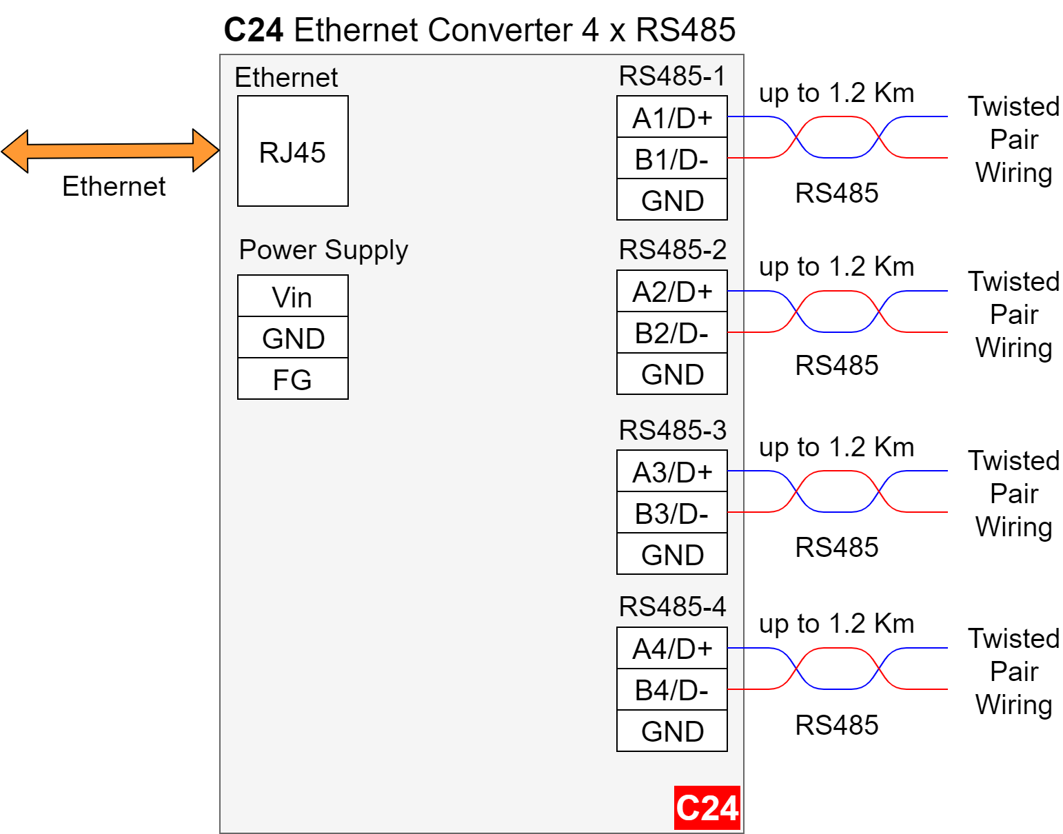
Transmission | RS485 | Max. 1,200 m at 9.6 kbps; Max. 400 m at 115.2 kbps | ||||||||
| Mounting and Enclosure | DIN Rail, Plastic PA - UL 94 V0, Black/Green | |||||||||
| Temperatures | -40°C to +75°C Operating and Storage | |||||||||
| Humidity | 10 - 90% RH, Non-Condensing | |||||||||
ESD Protection | ±4kV contact discharge / ±8kV air discharge | |||||||||
| Certification | CE, RoHS | |||||||||
Applications
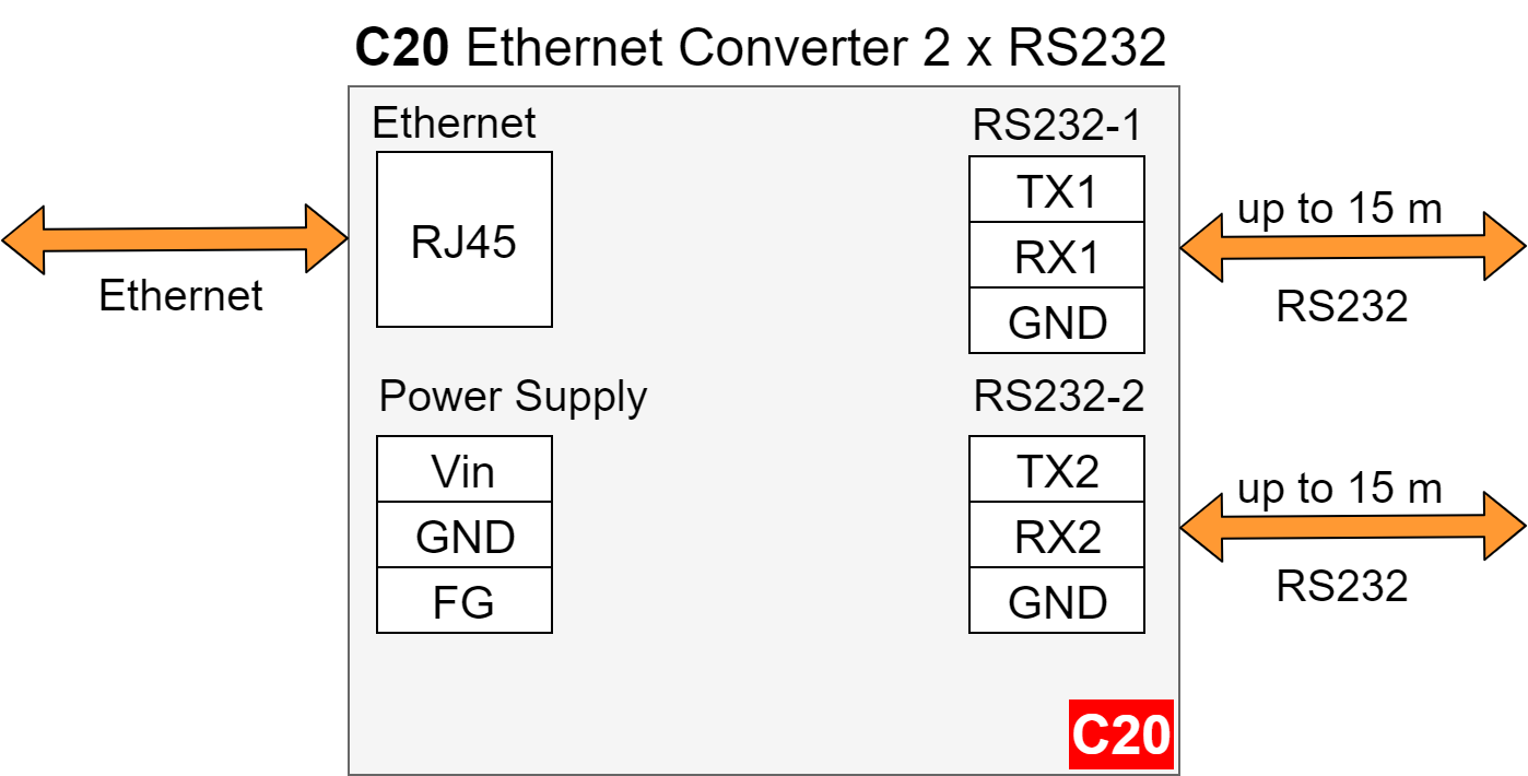
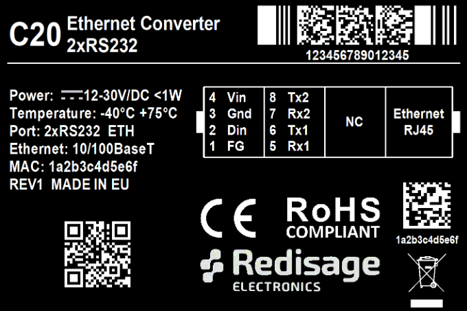
C20 - Ethernet Converter 2x RS232
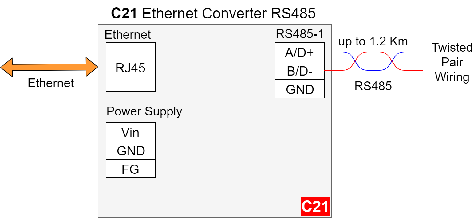
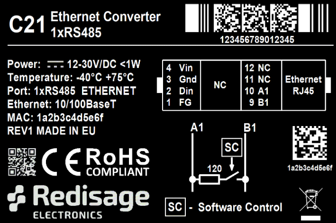
C21 - Ethernet Converter 2x RS485
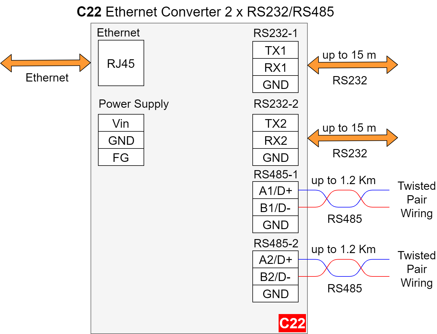
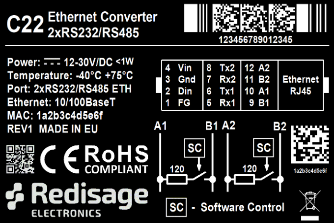
C22- Ethernet Converter 2x RS232/RS485
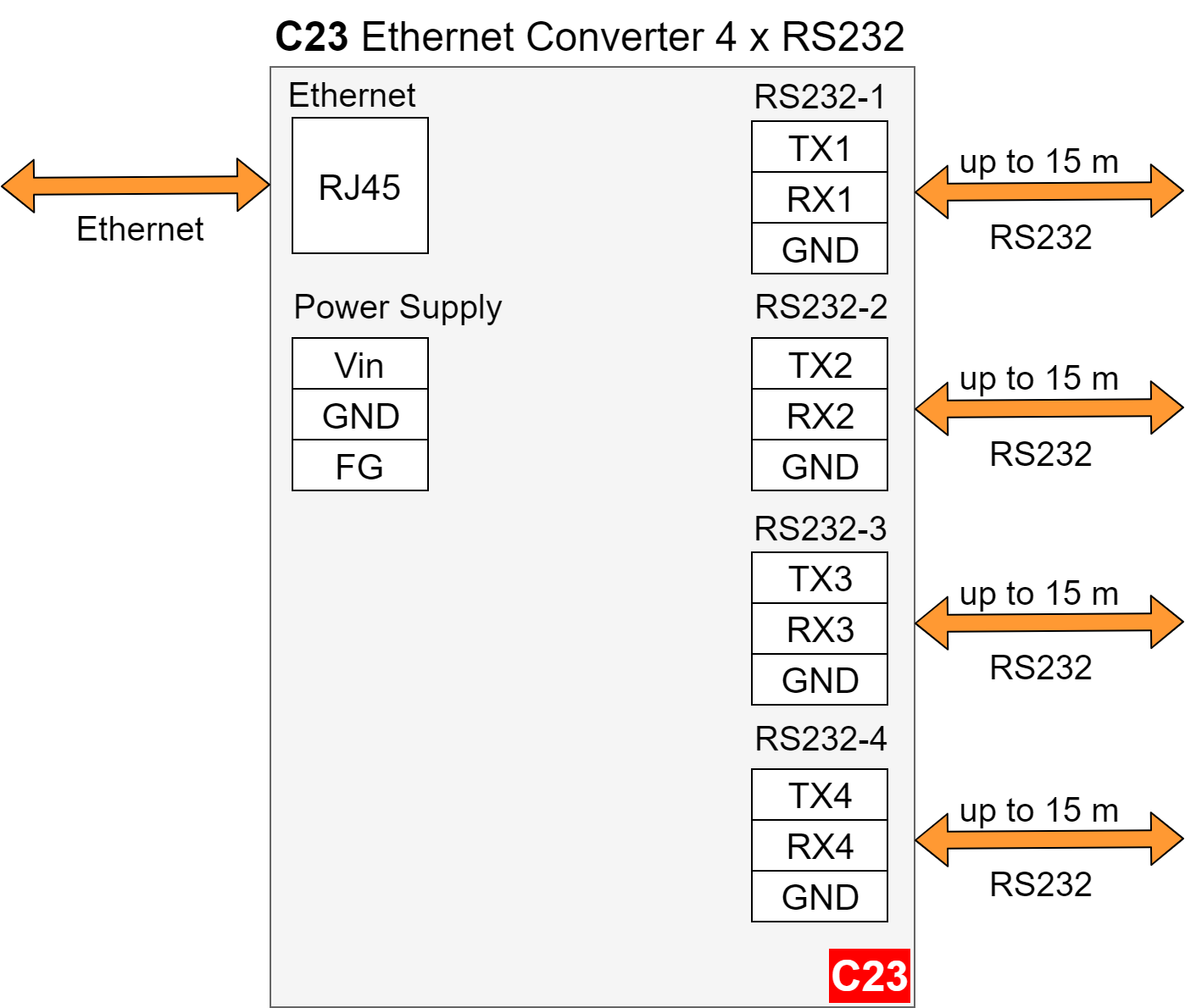
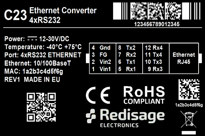
C23 - Ethernet Converter 4 x RS232
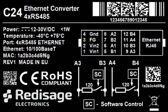
C24 - Ethernet Converter 4 x RS485
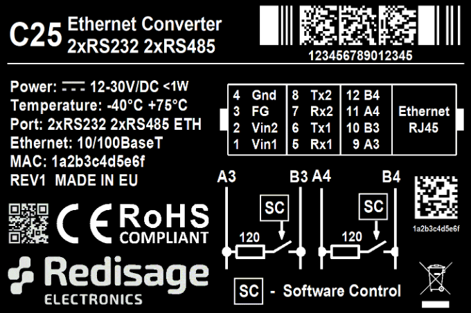
C25 - Ethernet Converter 2 x RS232/RS485

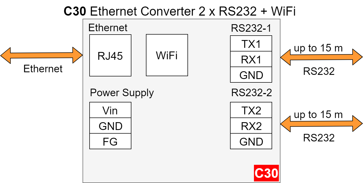
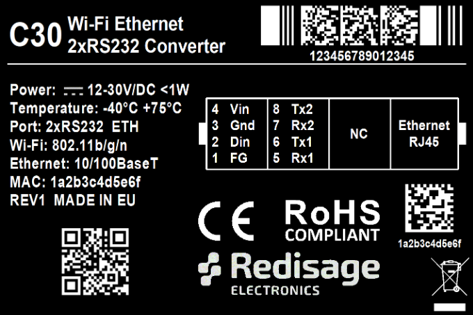
C30 - Ethernet Converter 2x RS232 + WiFi
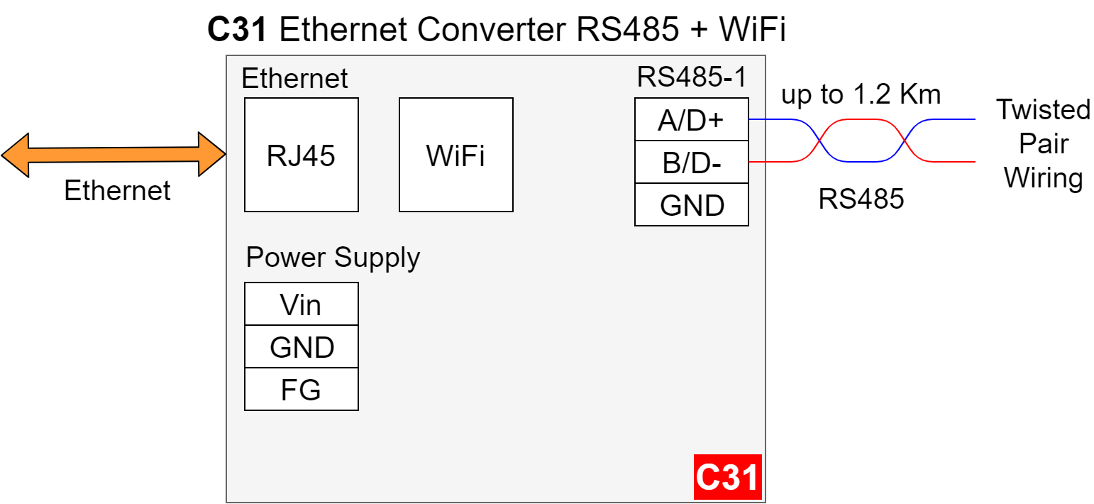
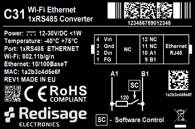
C31 - Ethernet Converter 2x RS485 + WiFi
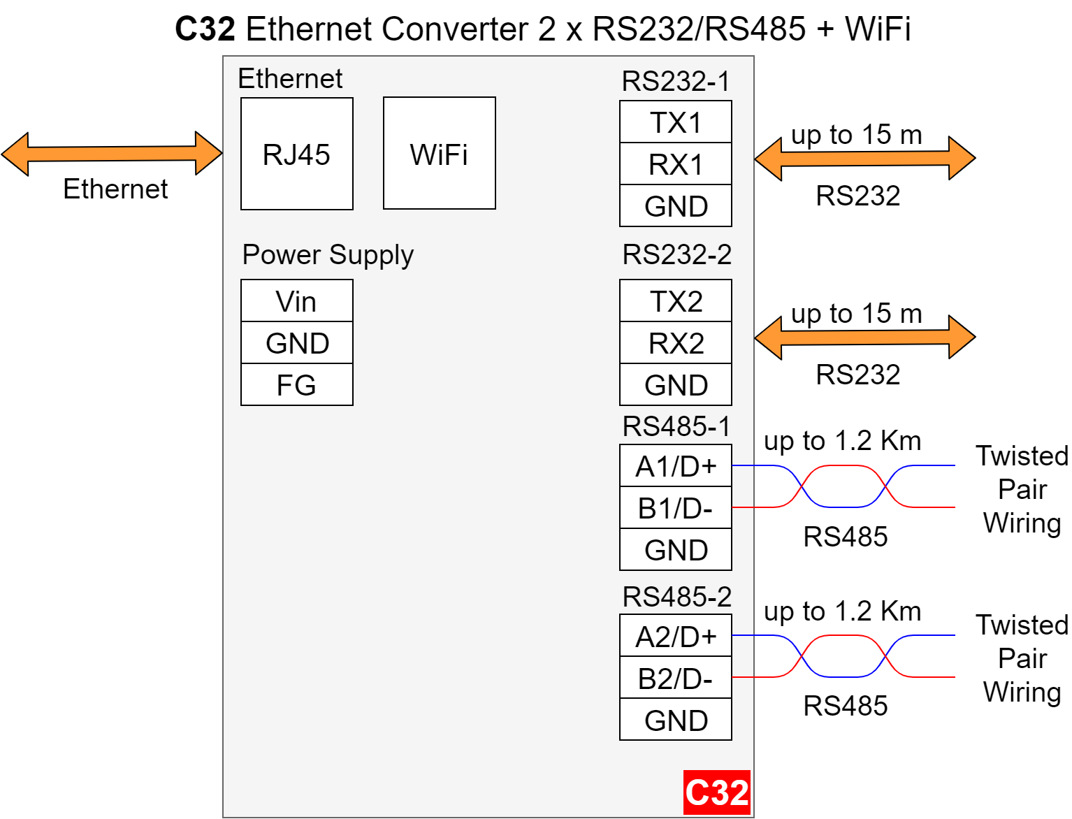
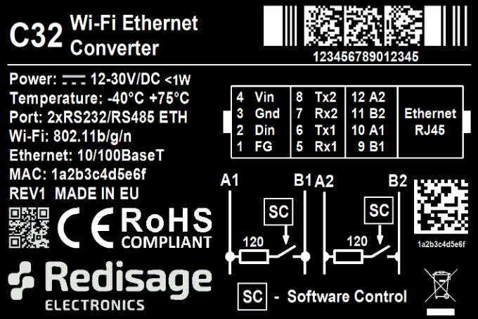
C32 - Ethernet Converter 2x RS232/RS485 +WiFi
Frame Ground FG
Electronic circuits are constantly prone to electrostatic discharge ESD.
Rediisage Electronics modules feature a design for the frame ground terminal block FG.
The frame ground provides a path for bypassing ESD, which provides enhanced static protection ESD abilities and ensures the module is more reliable.
Connecting FG terminal block to the earth ground will bypass the ESD disturbances outside the device so will provide a better level of protection against ESD.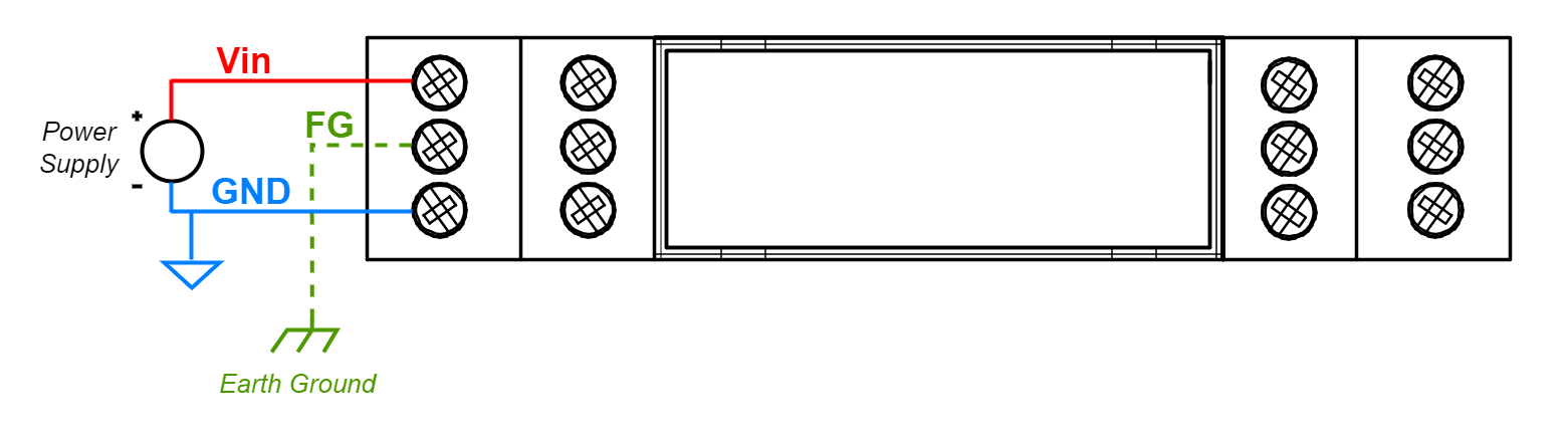
Frame Ground FG connection referece drawing.
If earth ground is not availabe FG can be left floating or can be connected with power supply GND.
Pin Assignments
C20
| C21
|
C22
| C23
|
C24
| C25
|
C30
| C31
|
C32
| |
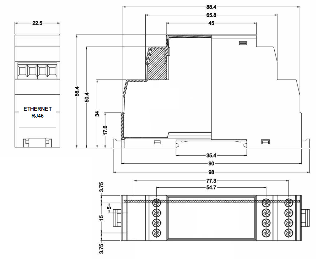
Enclosure Dimensions
2U Module Enclosure.
98 x 22.5 x 56.4
Units: mm.
3D Model
3D model for reference only !
Getting Started
Power Supply
Ethernet converters C20-C25 and C30-C32 have wide voltage power input 12-30 V/DC, the power consumption is less than 1 W.
LED Indicators
Ethernet converters C20-C22 and C30-C32 have 3 LED indicators:
PW LED Blue - Power
ETH LED Green - Network activity
ST LED Orange - USB-UART Serial console mode
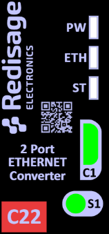
Fig. 1. Reference front label of C20-C22 and C30-C32
Ethernet converters C23-C25 have 5 LED indicators:
PW LED Blue - Power
ER LED Yellow - Error
ETH LED Green - Network activity
COM LED Green - RS232/RS485 activity
CN LED Yellow - Console mode
SR LED Red - Service mode
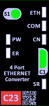
Fig. 2. Reference front label of C23-C25
Configuration by Web Page
Default configuration of ethernet converters:
IP adress: 192.168.100.100,
Subnet mask: 255.255.255.0
Gateway: 192.168.100.1
DNS 1: 192.168.100.1
DNS 2: 8.8.8.8
Default login details:
User name: admin
Password: admin123
The network configuration of the device can be changed through the serial console which is described in the Configuration by serial console section.
To access to web page open the web browser, type the IP address in the address bar, and log in using the default user name and password. The IP address of the device and PC must be in the same Local Area Network.
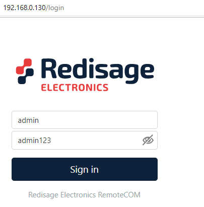
Fig. 3. Login panel on the web page
After successful login, the status page will show the current status of ports.
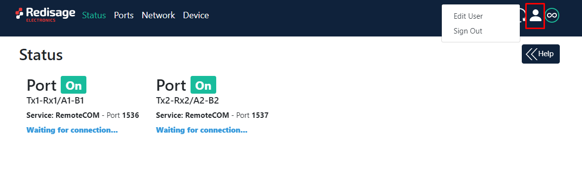
Fig. 4. Status page and edit user option
To change the user name and password click on the user icon and select edit user.
Ports configuration is possible on the ports page.
Ports Configuration:
Service determines how the port 'talks' over the network. Choosing RemoteCOM lets to attach the port to a computer running the Redisage Electronics VSP Client as if it was physically present in the computer. Choosing TCP/UDP Socket exposes this port as a regular network socket - connect to this socket with own software and write/read data to send/receive data over the serial port, without any additional software or serial port handling. TCP/UDP Socket exposes this port as a regular network socket - connect to this socket with own software and write/read data to send/receive data over the serial port, without any additional software or serial port handling.
Port is the service number - the device has an 'IP Address' by which it is identified, and a couple of services running on it. It's required to tell the device which service should be in use, by entering this device's IP address and the port number in the RemoteCOM client, or your software.
Termination enables/disables termination on the RS line.
Encryption determines how the data is protected 'in flight' over a network. It is available only with the RemoteCOM service. Once enabled, you'll have to set the Password.
Password protects the communication between the device and various clients - keep it secret! Same settings have to appear in clients - without the correct passwords, a client will not connect at all.
Baud Rate determines the port's transmission speed over the data channel.
Data Bits determine the number of data bits in the port's message frame.
Parity enables/disables parity check in the port's message frame.
Stop Bits determine the number of stop bits in the port's message frame.
Notes These notes are for information only - feel free to write down anything related to this port (device it connects to, etc.). They're also shown in the Configurator during the device discovery - in other words, they're public.
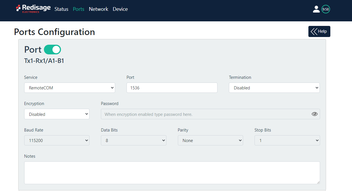
Fig. 5. Ports page
Network setting can be changed on the network page.
Hostname is the label that is assigned to the Device.
Configuration Method enables/disables the DHCP server. If the DHCP server is disabled, the IP Address of the Device has to be set manually.
IP Address of the Device.
Netmask associated with the IP Address.
Gateway address currently used by the Device.
DNS Address is the Domain Name System used by the Device.
Broadcasts notify RemoteCOM clients in the same network about this device's existence. With this enabled, the Configurator will automatically set most of the settings correctly for you. All you need to do is to pick the correct port.
MAC Settings allows setting the default MAC address or typing it manually.
MAC Address allows changing the physical address of the Device.
Services
HTTP port determines the port of the control panel.
Telnet Port allows connection with the device via Telnet.
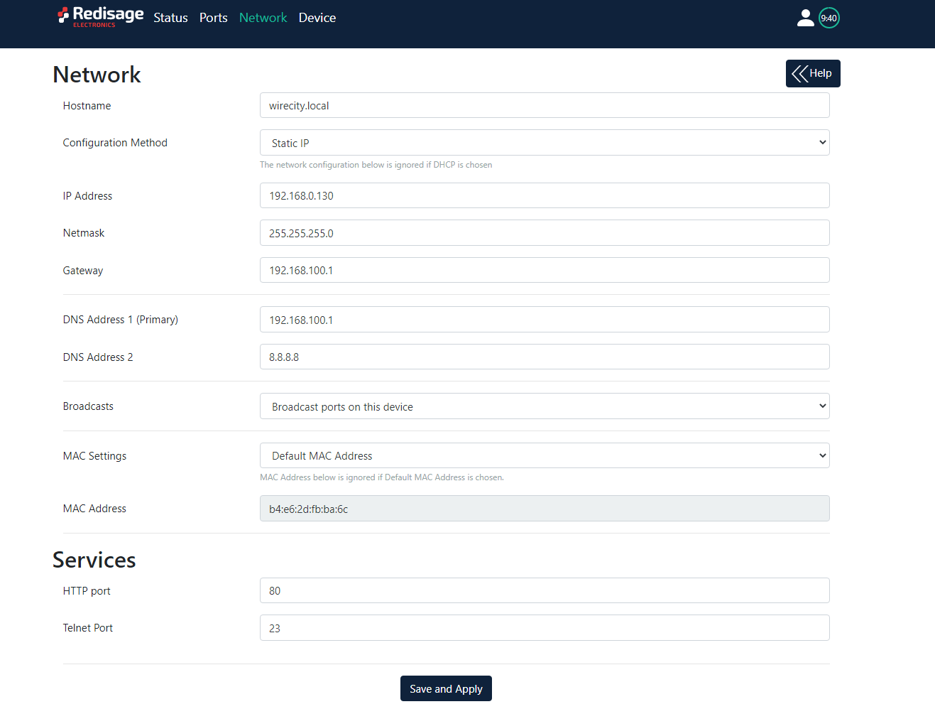
Fig. 6. Network page
On the device page there is informations about device and tools to factory reset, firmware uprgade and reboot device.
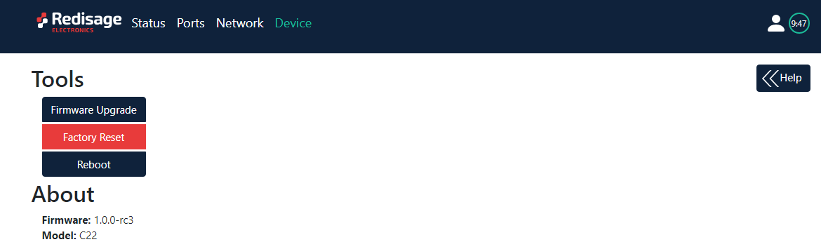
Fig. 7. Device page
Configuration by Serial Console
The device has the ability to be reconfigured via a serial console. C20-C23 and C30-C32 require a dedicated USB/UART converter connected to the USB micro-B connector on the front of the device. C23-C25 can be directly connected to a PC through a USB cable.
Procedure to enter serial console mode on C20-C23 and C30-C32:
- Turn off the power of the device
- Connect PC to the C1 micro-USB port using a dedicated USB/UART converter
- Press and hold the S1 button (or connect Din pin to GND pin if the button is not mounted)
- Turn on the power and wait a few seconds until the orange LED lights up
- Release the button (or disconnect Din pin from GND pin)
Procedure to enter serial console mode on C23-C25:
- Install STM32 Virtual COM Port Driver on your PC
- Turn off the power of the device
- Connect PC to the C1 micro-USB port using the USB cable (or use dedicated USB/UART converter)
- Press and hold the S1 button
- Turn on the power and wait a few seconds until the yellow CN LED lights up
- Release the button (or disconnect Din pin from GND pin)
Once this is done you can connect to the serial port. The baud rate of the serial port is 115200. Log in using the default username and password, then change the network settings using ipconfig command.
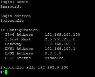
Fig. 8. Network IP change by serial console
List of all commands:
help - Prints the help.
conn - Print active TCP connections.
eth_mac - Print or change MAC address.
exit - Close current CLI session.
http_port - Print or change default http port.
ipconfig - Print or change the network configuration.
net_stat - Print lwIP statistics.
ping - Check internet connection with the desired host.
restart - Restart the system.
reboot - Same as restart.
sys_heap_usage - Print current heap usage.
telnet_port - Print or change default telnet port.
uart - Print or change uart configuration.
uart_service - Print or change uart_service configuration.
user - Print or change user configuration.
ipconfig available commands:
addr ADDRESS
Set IP addres to ADDRESS.
Example: ipconfig addr 192.168.0.10
mask NETMASK
Set subnet mask to NETMASK (in dot-decimal format).
Example: ipconfig mask 255.255.255.0
mask BIT_COUNT
Set subnet mask to BIT_COUNT bits.
Example: ipconfig mask 24
gateway GATEWAY_IP
Set network gateway to GATEWAY_IP.
Example: ipconfig gateway 192.168.0.1
dhcp enable|disable
Enable or disable DHCP client.
Example: ipconfig dhcp enable
dns1 ADDRESS
Set primary DNS to ADDRESS, disables getting DNS from DHCP if enabled.
dns2 ADDRESS
Set secondary DNS to ADDRESS, disables getting DNS from DHCP if enabled.
http_port available commands:
help
Print this help message
PORT_NUMBER
Set http port to PORT_NUMBER. A PORT_NUMBER value must be in range:
1-65535
Example: http_port 80
status
Print current http port
Example: http_port status
A current http port is 80
telnet_port available commands:
help
Print this help message
PORT_NUMBER
Set telnet port to PORT_NUMBER. A PORT_NUMBER value must be in range:
1-65535
Example: telnet_port 23
status
Print current telnet port:
Example: telnet_port status
A current telnet port is 23
uart available commands:
help
Prints this help message
list
Lists available uarts in system
Example:
uart list
0: baud: 9600 bits: 8 stop_bits: 1 parity: none (service console)
1: baud: 115200 bits: 8 stop_bits: 2 parity: odd (covered by cons.)
2: baud: 9600 bits: 8 stop_bits: 1 parity: none
3: baud: 1200 bits: 8 stop_bits: 2 parity: even termination: ON (R-COM)
3: baud: 38400 bits: 8 stop_bits: 2 parity: none termination: OFF
PORT_NUMBER baud BAUD
Set PORT_NUMBER baudrate to BAUD. BAUD value can be one of below
2400
4800
9600
14400
19200
38400
57600
115200
Example:
uart 1 baud 9600
WARNING: uart covered by console. Changes will take place after the reset
PORT_NUMBER bits BITS
Set bit length to BITS. BITS value can be one from below:
8
Example: uart 2 bits 8
PORT_NUMBER stop_bits STOP_BITS
Set stop_bits length to STOP_BITS. STOP_BITS value can be one from
below:
1
2
Example: uart 2 stop_bits 1
PORT_NUMBER parity PARITY
Set uart parity to PARITY. PARITY value can be one from below:
none
odd
even
Example: uart 3 parity even
PORT_NUMBER termination STATE
Set uart termination to new STATE. STATE can be one from below:
ON
OFF
Example: uart 3 termination ON
uart_service available commands:
help
Prints this help message
list
Lists of uarts services status
Example: list
1 state: ON service: Remote COM port: 1504 enc: YES
2 state: OFF service: TCP Socket port: 1510
3 state: OFF service: UDP Socket port: 1510
UART_NUMBER state STATE
Set UART_NUMBER state to STATE. STATE value can be one from below:
ON
OFF
Example: uart_service 1 state ON
UART_NUMBER service SERVICE
Set UART_NUMBER service to SERVICE. SERVICE value can be one from
below:
Remote COM
TCP Socket
UDP Socket
Example: uart_service 1 service TCP Socket
UART_NUMBER port PORT_NUMBER
Set UART_NUMBER port to PORT_NUMBER. PORT_NUMBER value can be any in the range:
1-65535
Example: uart_service 1 port 1501
UART_NUMBER enc ENC_STATE
Set UART_NUMBER encryption to ENC_STAE. ENC_STATE can be one form
below:
YES
NO
Example: uart_service 1 enc YES
If ENC_STATE is YES then it will ask for a new password for encryption
user available commands:
Print or change user configuration.
Subcommands:
help
Print help
Example: user help
mod_name USER_NAME NEW_NAME
Change the user name to NEW_NAME
It fails in case the name is used by another user
Example: user mod_name john bill
passwd USER_NAME
Change USER_NAME's password
Example:
user passwd john
Enter password:
****** <- here is entered password, but '*' appears instead
Note: Everyone can change the password for themselves
Configuration by Telnet Console
Access to the telnet console can be obtained using a serial terminal program. Configure the connection type to telnet, enter the IP address and telnet port number (23 by default).
Console commands are the same as described in the serial console section.
Virtual Serial Port for Windows
To configure the RemoteCOM ports use a Redisage VSP Configurator program.
Configuration procedure:
- Change the Device ports service to remoteCOM
- Set up a ports number
- Enable or disable encryption
- If encryption is enabled create a password
- In VSP Configurator, click add device and then set a COM number and service port
- If encryption is enabled enter a password
- Click save changes
- Connect to the configured serial COM port via terminal software

Fig. 9. Redisage VSP Configurator - adding a new port
Reset to Factory Defaults
Reset to factory defaults is possible on the web page in the device section or using service mode.
Steps to enter service mode on C23-25:
- Turn off the power
- Connect PC to the micro-USB port C1 using dedicated USB/UART converter
- Press and hold the S1 button
- Turn on the power and wait until the red SR LED starts blinking
- Release the button
- Connect to the device through a serial terminal, a baud rate of the serial port is 115200
- Use command defaults to reset application variables to defaults
Steps to enter service mode on C22-C25 and C30-C32:
- Turn off the power,
- Connect PC to the micro USB-B port C1 on the front of the device using a dedicated USB/UART converter
- Press and hold the S1 button (or connect Din pin to GND pin if a button is not mounted)
- Turn on the power and wait a few seconds until the ST LED starts blinking
- Release the button (or disconnect Din pin from GND pin)
- Connect to the device through the serial terminal, the baud rate of the serial port is 115200
- Use command defaults to reset application variables to defaults
Service mode commands:
help Prints the help.
credits Print current credits value for this device
dev_ident Print the device identification value.
restart Restart the system.
serial_num Print the serial number of this device.
version Display the bootloader version
xmodem Download image to the internal Flash using xmodem
defaults Reset application variables to defaults.
ipconfig Print or change the network configuration.
Related Information and Links | ||
|---|---|---|
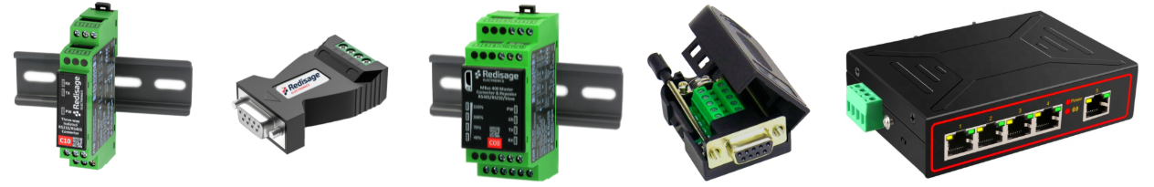
Ordering Information | Accessory | Similar Products |
Products Family Sample Photo
DISCLAMER NOTES
ALL PRODUCT, PRODUCT SPECIFICATIONS, AND DATA ARE SUBJECT TO CHANGE WITHOUT NOTICE TO IMPROVE RELIABILITY, FUNCTION OR DESIGN OR OTHERWISE.